Patch Clamp Pipette Diameter

Patch Clamp

DetailsManuals DownloadsImages and DataRelated Products
Pre-Pulled Glass Micropipettes
Patch Clamp Pipettes
Pre-Pulled Glass Micropipettes: Part No. PCPs-1A
Highlights:
Pipettes freshly fabricated for each order
Precise fabrication to specifications
Packaged for stable shipping and storage
Multiple applications including microfluidics, printing and patch clamping
Made in the United States
Pre-configured and custom configured micropipettes are available
Not fire polished
Additonal configurations are available; see part MGM-1 click here
Standard Pre-Pulled Glass Micropipettes
Pre-Pulled Micropipettes - Standard Configuration. 210 for 30 pipettes, 595 for 100 pipettes
Parameters, Part No PCPs-1A:
Glass: thin wall borosilicate, with or without internal filament
Total pipette length: Approx 5 cm
Outer diameter at tip OD : 1.5 0.3 µm
Inner diameter at tip ID : 1.2 0.24 µm
Taper length: 1-5 mm
Wall thickness at base: 0.17 mm
Outer diameter at base OD : 1 or 1.5 mm depending on request
Pipettes pulled on highly stable Sutter Instruments P-2000 laser puller
Specification Sheet
Quantity
Part No.
Cost USD
30 pipettes
PCPs-1A 30f with filament
210.00
PCPs-1A 30wf without filament
100 pipettes
PCPs-1A 100f with filament
595.00
PCPs-1A 100wf without filament
Select pipettes on available options menu.
For additional configurations for pre-pulled glass micropipettes, see Part MGM-1 click here.
For online orders, please write with or without filament in the comments box
Custom Pre-Pulled Micropipettes: Part No. PCPs-1B
Cost: 210 - 330 for 30 pipettes, depending on configurations. Lead time: 3 - 14 days
To inquire and/or order custom pipettes, contact customersupport fivephoton.com or Tel: 1.858.395.4026.
Applications: IVF, microinjection, focal saline application, cell collecting, voltage/current-clamp, single channel recordings, single cell pharmacology, microfluidics, microapplication on chip, molecular printing, micropipette applications.
Parameters:
Glass: Customer request
With or without internal capillary
Length: Customer request
Outer diameter OD : Customer request
Wall thickness: Customer request
Tip outer diameter: Customer request
Tip inner diameter: Customer request
Pipette resistance in standard saline : Customer reques
Pipette-Cell Image: Adult rat trigeminal mesencephalic neurons.
Representative Electrophysiology Recordings
3µM BRUS-3145 200nM omega-AgaIVA 5microM BRUS-3145
Figure Legends:
Upper panel demonstrates stability of Ca channels and potentiation effect of experimental substance BRUS-3145 recorded with patch pipettes produced by FIVEphoton Biochemicals isolated cortex neurons of rat. w-Aga-IVAdoes not block the BRUS-induced potentiation of the Ca channels. The cortex neuron which demonstrated the potentiation effect under the addition of 3mM BRUS-3145 was then incubated in 200nM w-Aga-IVA. Left panel: IVrelationships measured in control open circles and after application of 3mM BRUS-3145 filled circles. Right panel: IV relationships measured after 3 min incubation in w-Aga-IVA open triangles and after subsequent application of 3mM BRUS-3145 filled triangles. The recovery squares was obtained within 1 min in both cases.
Data – courtesy of Light Biologicals, Inc
Storage: Room temperature.
Lead time: 3 business days for standard pipettes.
Shipping recommendation: Domestic 3-day 15 flate rate, 2-day Fedex 35 flat rate or domestic overnight delivery 52 flat rate. Packing is stable for international delivery to South America, Canada, Europe, Middle East and Asia: please inquire with customersupport fivephoton.com for international shipping rate.
kw. pre-pulled glass micropipettes, borosilicate micropipettes, micropipettes, pre-pulled pipettes, pre-pulled capillaries, glass needles
Click to enlarge
Click to enlarge.
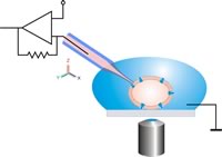
- Patch clamp recording uses a glass micropipette called a patch pipette as a recording electrode, and another electrode in the bath around the cell, as a reference.
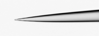
- Basic technique. Patch clamp traditionally uses a glass pipette, with an open tip diameter of about one micrometre, and is made such that the tip forms a smooth.
- Patch Clamp Pipettes Pre-Pulled Glass Micropipettes Pre-Pulled Pipettes PCPs-1; Total pipette length: Approx 5 cm; Outer diameter at tip.
- The patch-clamp technique allows the investigation of a small set The diameter of the pipette tip is around 1 µm which encloses a membrane patch that contains.
- Making Single Cell Pipets. To measure what s happening in or on a single, living cell, scientists use a technique called the patch clamp which requires an extremely.
Patch clamp technique is a technique in electrophysiology that allows the study of individual ion channels in cells. The technique is used to study excitable cells such as neurons, muscle fibers and the beta cells of the pancreas. It can also be applied to the study of bacterial ion channels in specially prepared giant spheroplasts. In classical patch clamp technique, the electrode used is a glass pipette, but planar patch clamp uses a flat surface punctured with tiny holes.
Patch clamp technique is a refinement of the voltage clamp. Erwin Neher and Bert Sakmann developed the patch clamp in the late 1970s and early 1980s. They received the Nobel Prize in Physiology or Medicine in 1991 for this work.
Basic technique
Patch clamp traditionally uses a glass pipette, with an open tip diameter of about one micrometre, and is made such that the tip forms a smooth surfaced circle, rather than a sharp point. This style of electrode is known as a patch clamp electrode and is distinct from the sharp microelectrode used to impale cells in traditional intracellular recordings. The interior of the pipette is filled with different solutions usually called the pipette solution depending on the specific technique or variation used see following. For example, with whole cell recordings, a solution that approximates the intracellular fluid is used. A metal electrode in contact with this solution conducts the electrical changes to a voltage clamp amplifier. The researcher can change the composition of this solution or add drugs to study the ion channels under different conditions. The patch clamp electrode is pressed against a cell membrane and suction is applied to the inside of the electrode to pull the cell s membrane inside the tip of the electrode. The suction causes the cell to form a tight seal with the electrode a so-called gigaohm seal, since the electrical resistance of that seal is in excess of a gigaohm.
Unlike traditional voltage clamp recordings, the patch clamp recording uses a single electrode to voltage clamp a cell. This allows a researcher to keep the voltage constant while observing changes in current. Alternately, the cell can be current clamped, keeping current constant while observing changes in membrane voltage.
Tay s method of patch clamping step by step
Secrets for patch clamping:
You must keep your electrode tip clean. This can be achieved by keeping all of your fluids clean and spending the least amount of time finding your electrode.
Your electrode tip must be the right size. If it is too small you will not be able to pass enough fluid through to keep the tip from touching the tissue and it will be difficult to break the patch usually above 8MOhms, if it is too large you will not be able to form a good seal.
Step by step patch clamping
Finding the electrode
Pull a glass electrode, fill it and mount on electrode holder
Choose a cell under 2x magnification and center it under the dot on the monitor, then set your magnification to 1x to get widest view for finding your electrode
Raise the objective by about 1/2 turn on the gross manipulator turning away from you
Line the electrode up so it is the same height as the chamber and move so that it is pointing to the focal point of the objective and centered
Place pressure on the electrode, just enough to keep the tip clear. This is about equivalent to a hard blow or 1/3-1/2 of a cc of air.
Move the electrode diagonally by 8500 according to the micromanipulator 8.5mm this is for our 20x objective
Move the electrode back and forth, if you don t see it advance the electrode by 1/2 turn. If you still don t find it after a few steps, widen your back and forth movements and check that it is in the center of your objective.
When you find your electrode place the tip over the dot on the monitor, then move it back along x axis until it is about 1/2 of the way between the dot and the edge of the screen
Lower your electrode and focus, keeping the focus advanced of the electrode, until the slice comes into focus
Patching the neuron
On the Multiclamp Commander MC, zero the electrode offset and set it to voltage clamp mode
Using MC, measure the resistance of the electrode should be around 5MOhms
Place the electrode at the right height above the cell to make a diagonal approach to reach the cell
Diagonally advance the electrode up to the neuron. If you miss, place the electrode directly above the neuron and lower the electrode down onto the neuron
Push the electrode up against the neuron until you see a dimple form
Release the pressure on the electrode
Immediately you should see a small rise in the resistance. Suck very gently until the resistance reaches 100 MOhms.
Once resistance has reached 100MOhms turn the MC to hold the electrode at -65 mV
Continue to suck until the resistance has reached 1GOhm
Once you have reached 1GOhm, give a short suck to break the membrane. Start with soft short sucks and increase strength until you see a change in the holding current
When you break through immediately turn off the resistance measurement, otherwise it make the neuron fire like crazy
Switch to current clamp mode and check if the resting potential is near -65mV
Inject a few current steps using the tuning set at 2 Hz and see if the neuron fires
Voila, you have patched a neuron
OK, I did everything right, but it still didn t work
What can go wrong with patch
Resistance is too high.
There is not enough fluid in your electrode and the wire in the electrode is not in the fluid
There is an air bubble in the electrode or the tip is clogged. You can correct this by blowing fluid out of the electrode.
If you are getting lots of crud in your electrode, it may be time to change the filter on the ICF syringe.
I can t find my electrode.
Really make sure your electrode is centered in the objective. When your electrode is almost in position, you can bring move it towards the objective until you see it bend, then back off.
The electrode could have hit something and broken on the way, if this is the case, just replace it and start over.
I can t seem to break the seal
Often, if you suck to strong to start with, you break the seal without knowing it and suck onto an organelle. If you pull the electrode out slowly you will see the nucleus attached to the tip. If this is the case, you must start with much softer sucks.
The electrode moves in the opposite direction from normal.
If your electrode is hitting the objective or a string on the banjo, it can be bent when you start. By moving down, the electrode tip will move up because it is on the other side of the fulcrum. If this occurs, raise the objective until the electrode is no longer bent and then recenter the electrode.
The Resistance is huge but my electrode is clean
The resistance is measured between the silver wire in the electrode holder to the ground. Ideally we are measuring it to the Ag/AgCl ground pellet in the chamber. As we pass current through the circuit, current oxidizes the Ag/AgCl pellet and wire. Eventually these get used up and need to be recharged or replaced. Test each of the following things to see if it corrects the problem.
There is a bubble in the electrode that is out of view. Try moving the focus of the electrode and seeing if you find it.
The water in the bath is touching the ground pellet at the back of the chamber. Occasionally the chamber will fill wihout wetting the pellet, just touch the pellet with a wet paintbrush and this should solve the problem.
The ground pellet is coupled to the headstage via a green wire. Check that this wire is connected to the pellet and into the back of the headstage.
The Ag/AgCl wire in the electrode holder has lost all of the AgCl salt and has become a high resistance interface. Rechloride the wire by removing the holder from the headstage and placing the wire in Chlorox Sodium hypochlorite for 15 minutes. It should look dark or grey but not shiny. Then wash and return to the headstage. This should be done fairly regularly, probably once a week when doing a lot of recordings
If the resistance keeps overloading this could be caused by voltage on the inputs from the Dyanmic Clamp. Test if the dynamic clamp has gone crazy by measuring if there is a significant voltage on the output channels. If there is, try turning off modules that might try to inject current. If nothing can remove a significant voltage then the board may need to be replaced. First reboot into windows and run the NI Diagnostic utility.
The Ag/AgCl pellet has been used up by passing a lot of current. This needs to be replaced. New pellets are in the Axon Drawer in a small plastic envelope. They have 2mm pins on one end and black with a silver pellet on the other. If we only have 1 or 2 left, order some more from Warner Instruments, the order number should be on the envelope. You will need to remove the stage from the microscope and cut the old one off the stage and glue the new electrode in with superglue. Let it dry and wash away the remaining oils before starting a new experiment. Otherwise you will coat the objective with superglue and it is very difficult to clean.
Electrode manipulator won t move to the spot I need to go to because it says EOR
This is caused by the manipulator getting confused about where it is located and thinking it is at the End of Range when it isn t. The solution is to reset the electrode manipulator. This can be done by swinging the holder out, so it won t crash into anything. Then push the button on the back of the box with the manipulator dials. The manipulator will move to all its extremes and reset itself
Variations
Several variations of the basic technique can be applied, depending on what the researcher wants to study. The inside-out and outside-out techniques are called excised patch techniques, because the patch is excised removed from the main body of the cell. Cell-attached and both excised patch techniques are used to study the behavior of ion channels on the section of membrane attached to the electrode, while whole-cell patch and perforated patch allow the researcher to study the electrical behavior of the entire cell.
Cell-attached patch: The electrode remains sealed to the patch of membrane. This allows for the recording of currents through single ion channels in that patch of membrane. For ligand-gated channels or channels that are activated through the action of drug molecules, the drug of choice is usually included in the pipette solution. While the resulting channel activity can be attributed to the drug used, it is not possible to then change the drug concentration. The technique is thus limited to one point in a dose response curve per patch. Usually, the dose response is accomplished through several cells and patches. However, voltage-gated channels or channels that are activated through changes in the potential across the membrane, can be clamped at different membrane potentials using the same patch. This results in graded channel activation, and a proper I-V current-voltage curve can be established with only one patch.
Inside-out patch: After the gigaseal is formed, the electrode is quickly withdrawn from the cell, thus ripping the patch of membrane off the cell, leaving the patch of membrane attached to the electrode exposing the intracellular surface of the membrane to the external media. This is useful when an experimenter wishes to manipulate the environment affecting the inside of ion channels. For example, channels that are activated by intracellular ligands like cGMP can then be studied through a range of ligand concentrations.
Whole-cell recording or whole-cell patch: The electrode is left in place, but more suction is applied to rupture the portion of the cell s membrane that is inside the electrode, thus providing access to the intracellular space of the cell. The advantage of whole-cell patch clamp recording over sharp microelectrode recording is that the larger opening at the tip of the patch clamp electrode provides lower resistance and thus better electrical access to the inside of the cell. A disadvantage of this technique is that the volume of the electrode is larger than the cell, so the soluble contents of the cell s interior will slowly be replaced by the contents of the electrode. This is referred to as the electrode dialyzing the cell s contents. Thus, any properties of the cell that depend soluble intracellular contents will be altered. The pipette solution used usually approximates the high-potassium environment of interior of the cell. Generally speaking, there is a grace period at the beginning of a whole-cell recording, lasting approximately 10 minutes, when one can take measurements before the cell has been dialyzed. Whole-cell recordings involve recording currents through multiple channels at once.
Outside-out patch: After the aforementioned whole cell patch is formed, the electrode can be slowly withdrawn from the cell, allowing a bulb of membrane to bleb out from the cell. When the electrode is pulled far enough away, this bleb will detach from the cell and reform as a ball of membrane on the end of the electrode, with the outside of the membrane being the surface of the ball. Outside-out patching gives the experimenter the opportunity to examine the properties of an ion channel when it is protected from the outside environment, but not in contact with its usual environment. In this conformation, the experimenter can perfuse the same patch with different solutions, and if the channel is activated from the extracellular face, a dose-response curve can then be studied. Single channel recordings are possible in this conformation if the bleb of membrane is small enough. This is the distinct advantage the outside-out patch variation possesses relative to the cell-attached method. However, it is more difficult to accomplish as more steps are involved in the patching process.
Perforated patch: In this variation of whole-cell recording, the experimenter forms the gigaohm seal, then adds a new solution to the electrode containing small amounts of an antibiotic, such as Amphothericin-B or Gramicidin into the electrode solution to punch small perforations on the bit of membrane attached to the electrode. This has the advantage of reducing the dialysis of the cell that occurs in whole cell recordings, but also has several disadvantages. First, the access resistance is higher access resistance being the sum of the electrode resistance and the resistance at the electrode-cell junction. This will decrease current resolution, increase recording noise, and magnify any series resistance error. Second, it can take a significant amount of time 10-30 minutes for the antibiotic to perforate the membrane. Third, the membrane under the electrode tip is weakened by the perforations formed by the antibiotic and tends to rupture. When the patch ruptures, the recording is essentially in whole-cell mode, except with antibiotic inside the cell. All of these problems tend to limit the time-length of experiments, and so this technique is most appropriate for short-duration experiments of about an hour.
See also
Working with SPF Animals - RAR facility
Setting up patch clamp puller.
Patch clamp techniques for single channel and The tip diameter of pipettes may be estimated before and after the initial pipette Patch clamp techniques 71.